From the free course AP Chemistry on Lykke
2.5 Lewis Diagrams · 2.6 Resonance and Formal Charge
Key concepts: Lewis diagrams · Resonance and formal charge · Octet rule · Formal charge as a structure-selection criterion · Limitations of the Lewis structure model · VSEPR theory · Bond orders · Bond polarities · Molecular structure and properties · Valence electrons
A Lewis diagram represents valence electrons as bonding pairs and nonbonding pairs, turning invisible electron arrangements into a model that can predict molecular structure and properties.
2.5 Lewis Diagrams · 2.6 Resonance and Formal Charge
A Lewis diagram represents valence electrons as bonding pairs and nonbonding pairs, turning invisible electron arrangements into a model that can predict molecular structure and properties. The key question is not merely “Can this structure be drawn?” but “Which drawing best represents the electron distribution?”
Building a Lewis diagram
A bonding pair is shown as a line between atoms; a lone pair is a pair of valence electrons located on one atom and not shared in a bond. The octet rule states that many main-group atoms are especially stable when surrounded by eight valence electrons, although hydrogen follows a duet rule and some atoms, such as aluminum, can be electron-deficient.
To construct a Lewis diagram, count the total valence electrons, select a reasonable skeletal arrangement, connect atoms with single bonds, complete terminal-atom octets, place remaining electrons on the central atom, and create multiple bonds if the central atom lacks an octet. For an ion, add electrons for a negative charge and remove electrons for a positive charge.
Worked example: nitrate, $NO_3^-$
Count valence electrons:
$$ 5+3(6)+1=24\text{ electrons} $$
Place nitrogen in the center and connect it to three oxygen atoms with single bonds. Those bonds use $6$ electrons. Completing the three oxygen octets uses $18$ additional electrons, leaving no electrons for nitrogen’s octet. Convert one oxygen lone pair into a second $N-O$ bond. Nitrogen now has an octet, and the structure contains one $N=O$ bond and two $N-O^-$ bonds.
The formal charge of an atom is the charge it would have if bonding electrons were divided equally:
$$ \text{Formal charge}
V-\left(N+\frac{B}{2}\right) $$
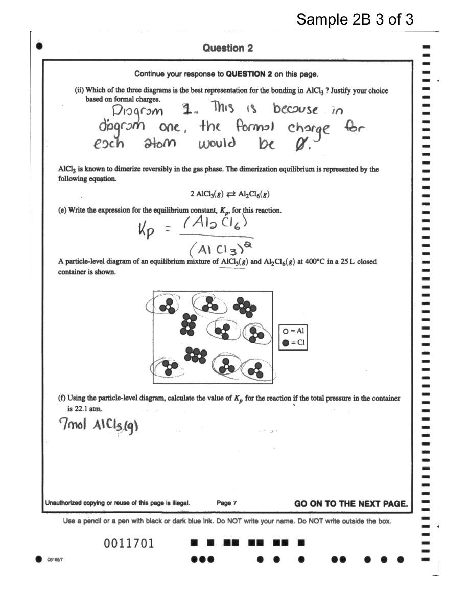
Here, $V$ is the atom’s valence-electron count, $N$ is its number of nonbonding electrons, and $B$ is the number of bonding electrons. In one nitrate contributor, the double-bonded oxygen has formal charge $0$, the two single-bonded oxygens each have formal charge $-1$, and nitrogen has formal charge $+1$. The total is $-1$, matching the ion’s charge.
Resonance: several drawings, one delocalized structure
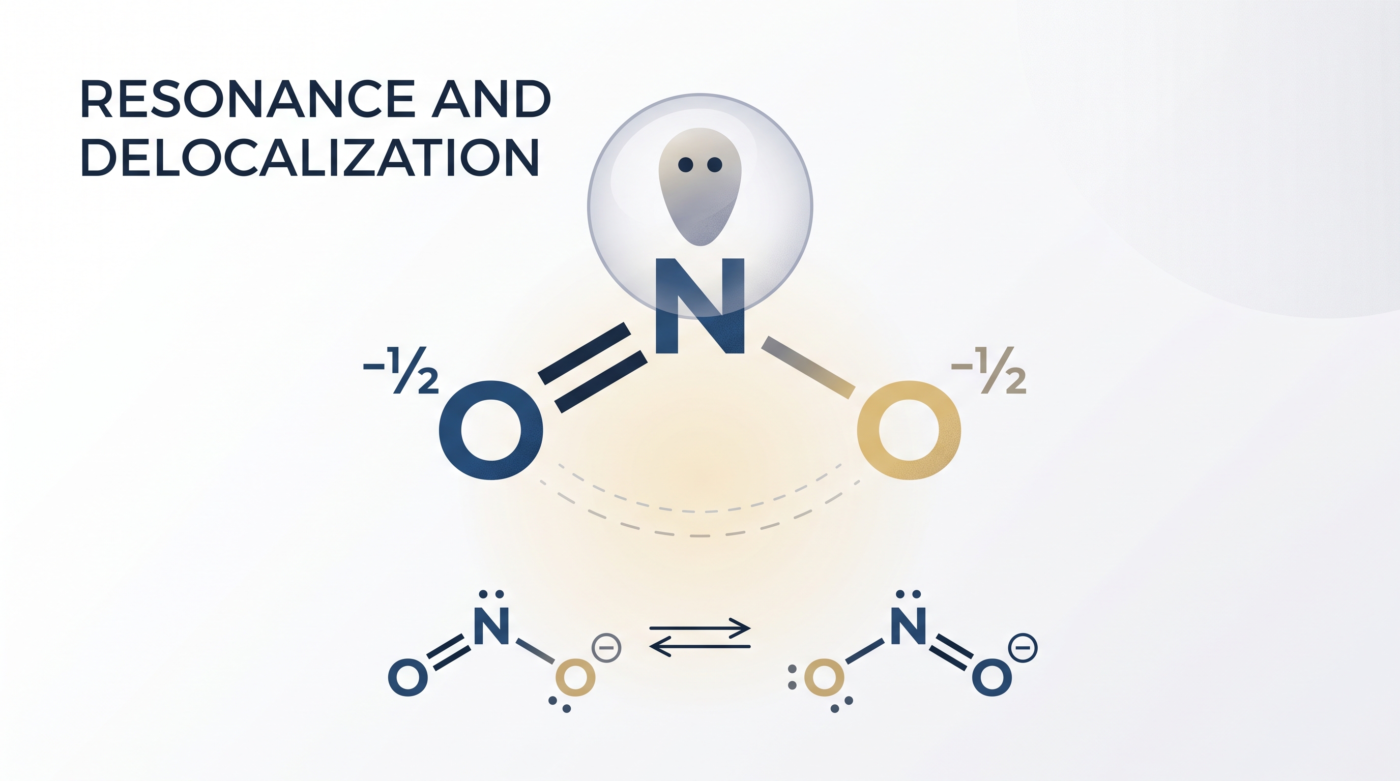
When equivalent Lewis diagrams differ only in the location of a multiple bond or charge, they are resonance structures. The molecule does not rapidly switch between these drawings. Instead, the actual electron distribution is a resonance hybrid in which electrons are delocalized over multiple atoms.
Nitrate has three equivalent resonance structures because the $N=O$ bond can be placed to any one of the three oxygen atoms. Consequently, all three $N-O$ bonds are equivalent in the real ion, with an average bond order of approximately
$$ \frac{4}{3} $$
This refinement is required by 2.6.A.1: resonance often gives qualitatively more accurate predictions of molecular structure and properties than any single Lewis contributor. Curved arrows may show electron movement between contributors, but the atoms themselves do not move.
Choosing among nonequivalent structures
Resonance contributors are not always equivalent. When possible structures differ in formal-charge placement, use the octet rule and formal charge together, as required by 2.6.A.2.
A strong candidate generally:
- gives main-group atoms complete octets when reasonable;
- minimizes the magnitude and number of formal charges;
- places negative formal charge on the more electronegative atom;
- avoids unnecessary charge separation.
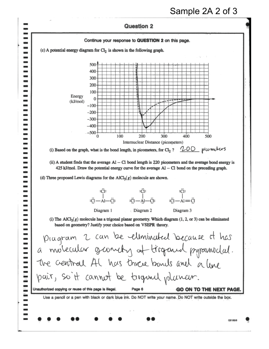
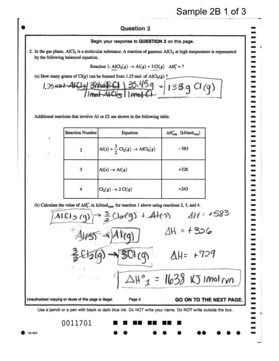
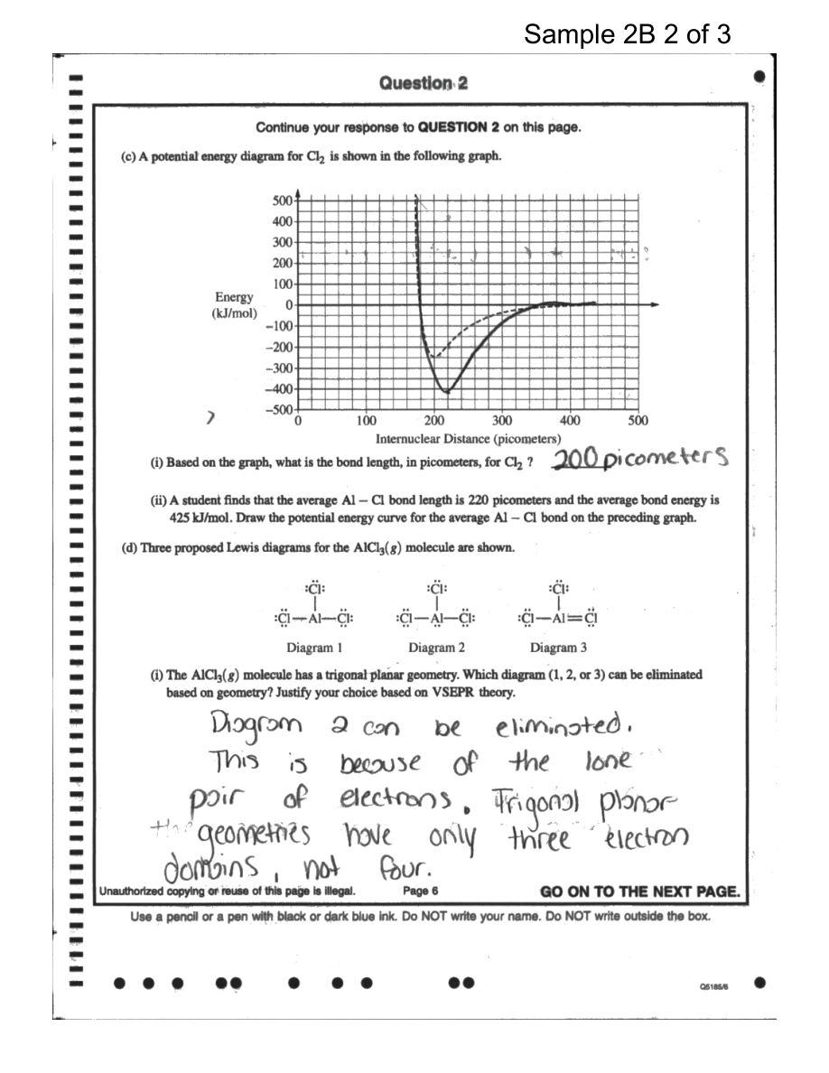
These are criteria, not absolute laws. A structure with an incomplete octet can be the better model when the central atom is electron-deficient, as in gaseous $AlCl_3$. A trigonal-planar $AlCl_3$ molecule has three bonding electron domains around aluminum. A proposed diagram containing an aluminum lone pair would create four electron domains and therefore cannot match that geometry.
Lewis diagrams and VSEPR
VSEPR theory, or Valence Shell Electron Pair Repulsion theory, predicts that electron domains around a central atom arrange themselves as far apart as possible because electron regions repel one another. A single bond, double bond, triple bond, or lone pair each counts as one electron domain; lone pairs usually repel more strongly than bonding pairs.
Lewis diagrams therefore provide the electron-domain count used for a first qualitative geometry prediction. For $AlCl_3$, three bonding domains and no lone pairs suggest a trigonal-planar arrangement. Detailed molecular shapes and hybridization follow from this electron-domain analysis, but the essential connection is simple: Lewis diagrams show the domains; VSEPR explains their spatial arrangement.
Bond polarity and model limitations
A polar bond forms when bonded atoms have unequal electronegativities. The more electronegative atom attracts shared electrons more strongly and becomes partially negative, written $\delta^-$; the other becomes partially positive, written $\delta^+$. Formal charges describe an idealized whole-number electron accounting, whereas partial charges describe unequal sharing.
Resonance can spread charge and bond character across several atoms. In nitrate, no single oxygen permanently carries the double bond or the entire negative-charge pattern; the delocalized distribution makes the three bonds equivalent and influences the ion’s polarity. Molecular polarity also depends on whether individual bond dipoles cancel through the molecule’s geometry.
Lewis structures are models, not photographs of electron density. They work especially well for counting valence electrons, identifying bonding and lone pairs, and making qualitative predictions, but they cannot represent delocalization perfectly. Their limitations are especially important for species with an odd number of valence electrons, because one electron cannot be paired into a conventional octet; such species are commonly described as radicals. This limitation is specified by 2.6.A.3.
AP science practices in action
This topic most directly develops Science Practice 1: Models and Representations, by constructing and revising Lewis diagrams; Science Practice 4: Model Analysis, by judging octet completion, resonance, formal charge, and model limitations; and Science Practice 6: Argumentation, by using those features as evidence for a structural claim. It also uses Science Practice 5: Mathematical Routines when counting valence electrons or calculating formal charge.
The official learning objective is 2.6.A: “Represent a molecule with a Lewis diagram that accounts for resonance between equivalent structures or that uses formal charge to select between nonequivalent structures.” A complete scientific argument should therefore state a claim, cite the relevant Lewis or VSEPR evidence, and explain why that evidence supports the predicted structure or property.
Retrieval check
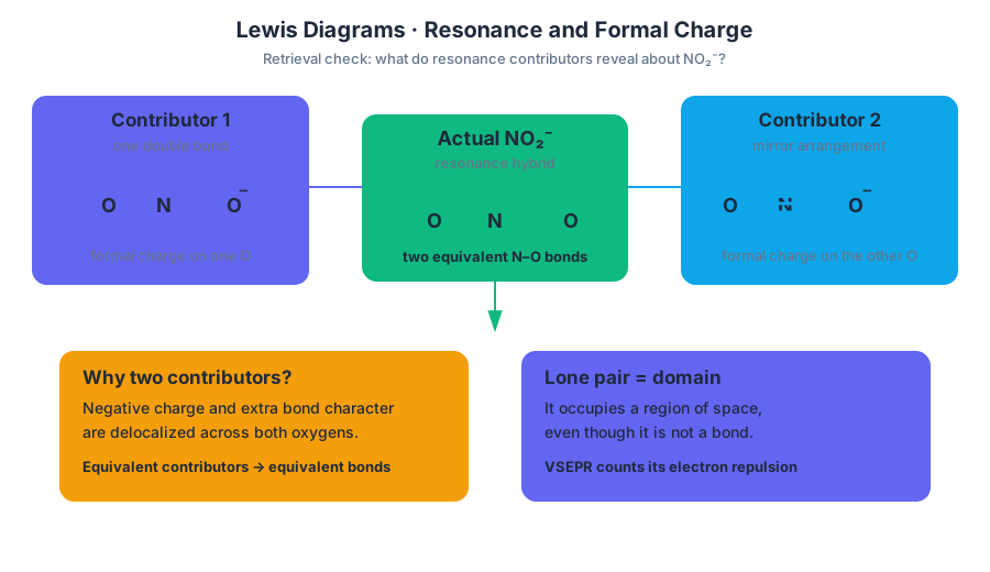
For $NO_2^-$, predict how many equivalent resonance contributors are possible and explain why the two $N-O$ bonds are equivalent in the actual ion. Then answer: why does a lone pair count as an electron domain even though it is not a bond?
Check: There are two equivalent contributors, so the negative charge and extra bond character are delocalized across both oxygens; the actual $N-O$ bonds are equivalent. A lone pair occupies a region of space and repels other electron regions, so VSEPR counts it as one electron domain.
Source Materials
- AP Chemistry Course and Exam Description
- AP Chemistry Course and Exam Description Clarifications and Corrections
- AP Chemistry Course Overview
- AP Chemistry Course at a Glance
- AP Chemistry Course at a Glance Poster
- Adopt AP Chemistry
- AP Chemistry
- AP Chemistry
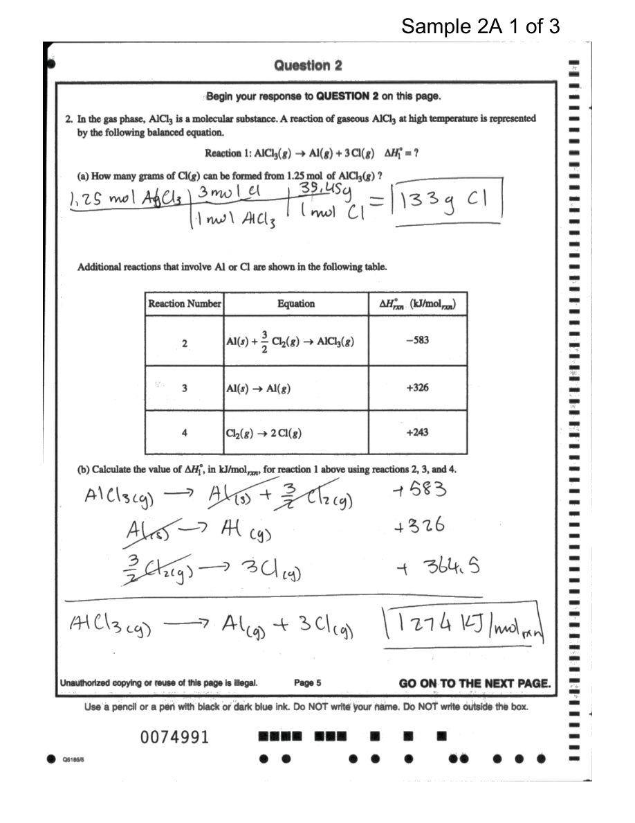
- Figure — Sample Responses Q2 (p. 4)
- Figure — Sample Responses Q2 (p. 5)
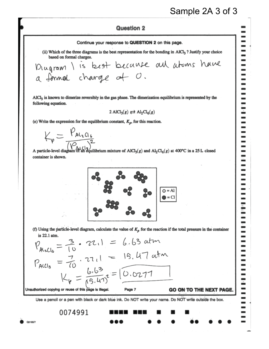
- Figure — Sample Responses Q2 (p. 6)
- Figure — Sample Responses Q2 (p. 7)